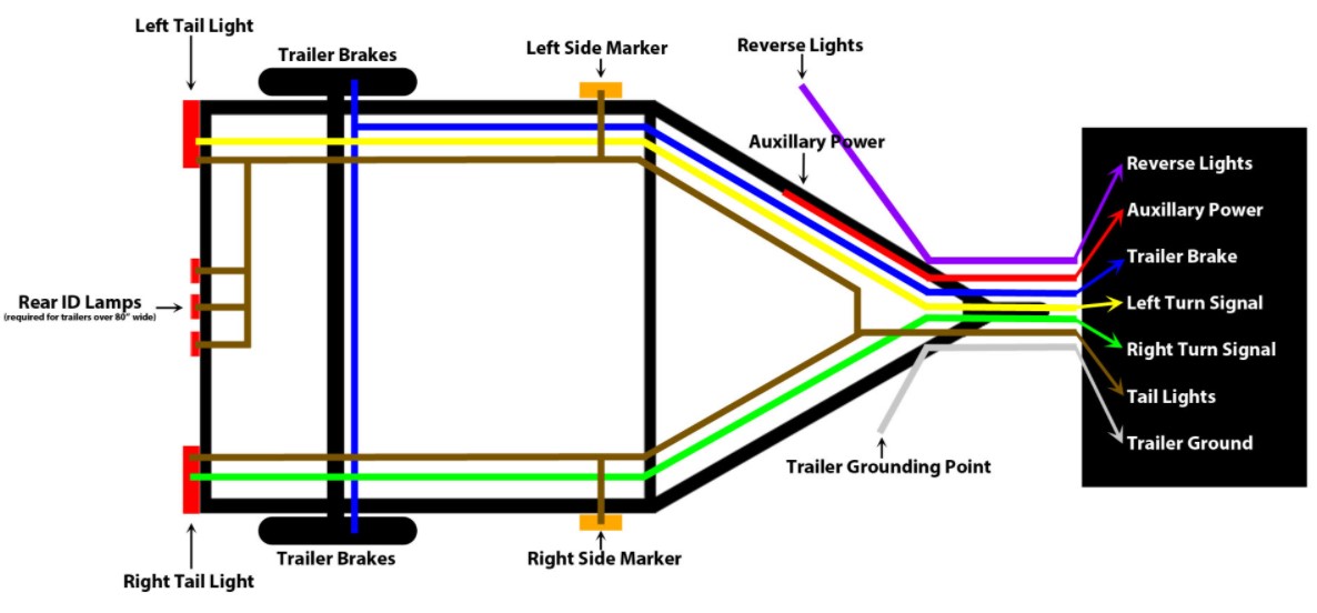
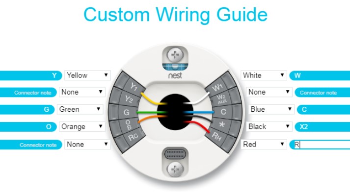
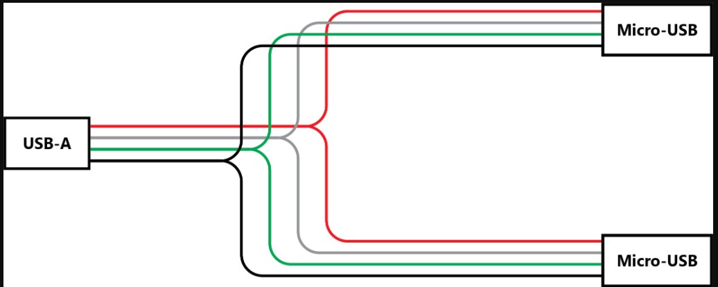
Wiring Diagram – Trailer, Nest, USB, and More – A wiring diagram is an ordinary pictorial representation of a complex electrical circuit. It depicts the components of the circuit in simplified form, with the electric power and various signal connections via the various terminals. Electrical wiring diagrams may also be referred to as electrical diagrams or just DDI. The term ‘Wired’ is derived from the Wires’ sense of being connected, which was first suggested by English Physicists in the late 19th century. The term is often used in modern electrical engineering, where it denotes a set of wiring principles, particularly those related to data transfer in networks.

There are different symbols used in a wiring diagram. There are numbers on the diagrams to indicate the connections in the circuit, alternating symbols to show the sources of power in the circuit, and then there are commutators to identify the path of different signals in the circuit. Some electrical wiring diagrams use only numbers and symbols, whereas others may also have commutators and alternating symbols. The difference between these two is that the symbols on the diagrams to identify the sources of power, whereas commutators identify the paths of signals. It is the use of symbols in a wiring diagram that has led to the term ‘Wired Electrical Diagram’. Another term that is commonly used is ‘Binary Electronic Diagram’ or BED.
A block diagram is a simple graphical representation of a complex electrical circuit. The component block diagrams of a circuit are typically very simple because all the parts of a complex circuit are usually placed in one place. The components of a block diagram are also shown as a single dot, as in a power source and its terminal, or as two dots, one for power and one for ground. In some cases, however, even a single component block diagram can be complex, especially if there are many different components in the circuit. A typical block diagram of a power distribution system will show power from different units distributed throughout a building.

Interconnection diagrams show the relationships among electrical circuits. These can be complicated and time-consuming to create because each connection needs to be carefully considered. The most common interconnection types are cable and grounding wire connections. Sometimes these are combined with shield bus wiring diagrams to represent the relationships among electrical circuits with more than one connection. Shield bus wiring diagrams are used to connect devices that are protected from each other by a grounded conductor.
A Wiring Diagram may be drawn manually using a pen and paper or it can be digitally drawn using WYSIWYG (what you see is what you get) tools that allow you to see the drawing almost instantly. There are a number of software programs available today that help you draw wiring diagrams in various formats. This tool can help make drawing a wiring diagram easier because the different symbols and connections are automatically indicated. You can also save your drawing in several different formats, including Microsoft Word, PDF, and JPEG.

A Wiring Diagram is not just useful for designing electrical circuits, but it is also very useful for troubleshooting problems in an electric current system or for analyzing electrical systems. Wiring diagrams can also be printed and placed on external panels for a wide range of purposes. Electrical wiring diagrams can help teachers and other consumers to understand electrical circuits and how they function. You don’t have to have the extensive technical experience to draw an effective and clearly readable Wiring Diagram. All you need is the ability to follow basic instructions and a few basic tools.