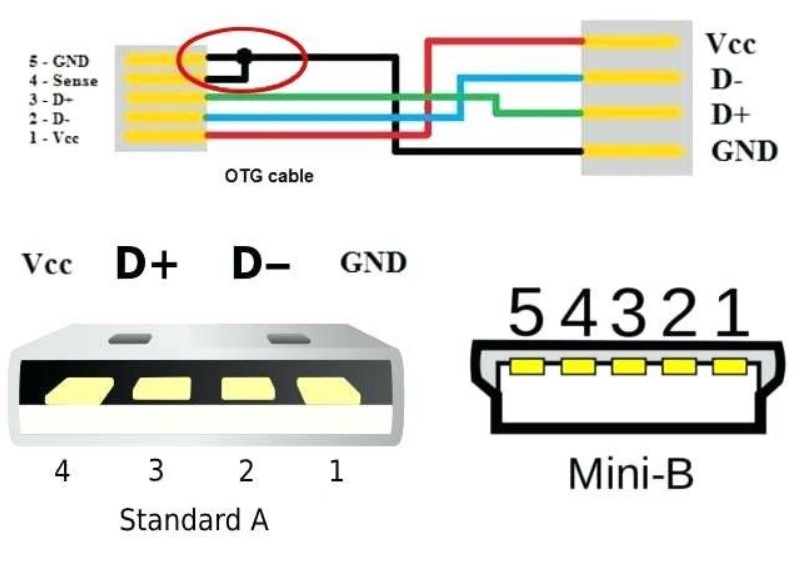
A USB Wiring Diagram shows the internal and external connections of a computer or peripheral device. It shows all the necessary connections from the computers or peripheral device to the accessory device. The two horizontal lines on the diagram show the analog data lines, that carry the instructions for the device to execute the desired function.
Each of the major pins of the USB connector is classified as an A-B-C pair. Each pair connects to a USB port and has its respective direction. The pins in each pair differ in polarity. The USB Wiring Diagram shows the USB data lines as vertical dotted lines, i.e., VCC to Ground, D2 to +VCC, GND to Ground, and USB to +VCC. For instance, when you connect a printer to a computer, the D2 is connected to the USB port on the computer, D+VCC is connected to the ground.

In a USB Wiring Diagram, the black colored pin connectors are the power sources of the peripheral device or computer. The red-colored ones are the data lines of the micro USB connector, and the green ones are the ground connections. The two power lines join to form a VCC to Ground connection. The pins of the Wiring Diagram are connected to form a junction, and the junction TEC is placed between the two wires to make a complete Wiring diagram.
Each of the major pins in a USB Wiring Diagram must be labeled with a unique color code. The primary colors for the connections are Black, red, blue, cyan, green, orange, and yellow. For instance, if it is a printer, the black colored cable is labeled with “BK” which stands for Black Label Circuitry. If the Wiring diagram is a mouse, then the blue and the green wires are labeled as “CP”. Each color code on a USB Wiring Diagram can stand alone or can be combined together with other colors.
The first thing that any good USB Wiring Diagram has been a unique color code for each wire. Each different color coding means a different data signal. For instance, the “green” color code for the differential data pin is used to signify positive or negative. When one inserts a pin into a USB connector, it is only halfway to fulfilling one’s goal. It is necessary to get both sides of the connector to touch the surface that will receive the power to signal that the device expects to send. In order to do this, a wire needs to be connected between the ground and the +5V outputs.
The most important thing when using a USB Wiring Diagram is making sure that there are no copper traces left in your electronic device. This is very easy to accomplish, all you need to do is get a continuity tester, and place it over the connection. If you see a small resistance, this means there is a copper trace, and that is why a continuity tester is not required. With a good quality USB micro b connector, this shouldn’t be a problem at all. There are several different types of USB connectors, but the main purpose is the ease of using them, and for data transfers, it couldn’t be easier.